Einen Steckstuhl beschnitzen
- Details
- Hauptkategorie: Schnitzen
 Im Oktober 2016 hatte ich Gelegenheit an einem HolzWerken-Leserseminar der Firmen Bosch und Bessey in Leinfelden teilzunehmen. Die vielen Detailinformationen zu Powertools und Spanneinrichtungen waren kaum zu verarbeiten! Glücklicherweise durften alle Teilnehmer umfangreiches Katalog- und wertvolles Informationsmaterial mit nach Hause nehmen! Das Highlight des ersten Tages war dann eine Besichtigung der Produktionsstätte "Bosch-Powertools" - Leinfelden. Noch spannender fanden die meisten Teilnehmer aber Tag 2. Da ging es nämlich ans praktische Ausprobieren: Jeder Teilnehmer hatte die Möglichkeit, einen einfachen Steckstuhl zu bauen. Auch Bosch und Bessey wollten dazulernen: Sie schauten uns beim Umgang mit den unterschiedlichen Elektrowerkzeugen und Spanneinrichtungen genau auf die Finger und notierten eifrig, was es aus unserer Sicht zu loben oder zu tadeln gab! Eine Win-win-Situation!
Ein Spinnrad nachbauen
- Details
- Hauptkategorie: Drechseln
 Das ausgeliehene alte Spinnrad steht als Referenzobjekt auf meiner Werkbank. Jedes Detail habe ich mir genauestens angesehen, ausgemessen, skizziert und mir Gedanken gemacht, welche Probleme beim Anfertigen der einzelnen Teile entstehen könnten.
Dummy-Taucherflaschen anfertigen
- Details
- Hauptkategorie: Modellbau
 Klar, richtig Tauchen kann man mit Pressluftflaschen aus Holz und Pappe natürlich nicht! Aber wozu sollen sie dann taugen? - Um diese Frage zu klären, müssen wir tiefer in die faszinierende Welt der Scuba diver eintauchen:
Holzhut drechseln
- Details
- Hauptkategorie: Drechseln
 Wer - wie ich - als gut "behütetes" Einzelkind aufgewachsen ist, möchte auch im Alter gut "behütet" sein. Und: Wer - wie ich - schon als Kind an Vaters Drechselbank üben durfte, sollte doch irgendwann im Stande sein, sich für sein - längst kahl gewordenes - Haupt einen passenden Hut zu drechseln!
Hölzernes Modell-Solowheel
- Details
- Hauptkategorie: Modellbau
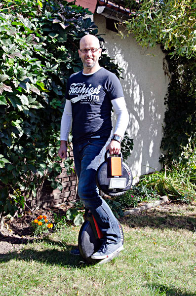 Schon öfter haben sich Rat-Suchende an mich gewandt. Aber Carsten kommt diesmal offenbar als Rad-Suchender: "Kannst Du mir bitte ein Solowheel-Modell drechseln?" - Ich möchte nicht zugeben, dass ich nicht weiss, was er mit "Solowheel" meint, also sage ich erst mal spontan zu.